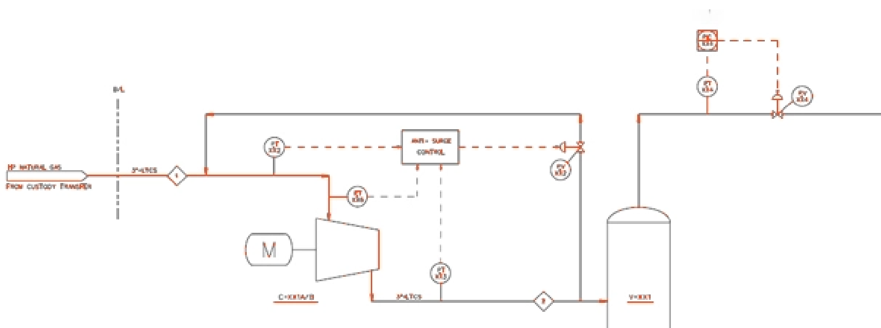
A Piping and Instrument or instrumentation drawing (P&ID) comprises more details than a PFD. It is developed based on information from process flow diagrams, which is developed based on a Block flow Diagram. A P&ID drawing includes both major and minor details of the process plant.
A piping and instrumentation diagram (P&ID) is a detailed diagram in the process industry which shows the piping and process equipment together with the instrumentation and control devices.
Piping and instrumentation diagram includes:
Pressure vessels, columns, tanks, pumps, compressors, heat exchangers, furnaces, wellheads, fans, cooling towers, turbo- expanders, pig traps (see 'symbols' below)
Bursting discs, restriction orifices, strainers and filters, steam traps, moisture traps, sight-glasses, silencers, flares and vents, flame arrestors, vortex breakers, eductors
Pipe classes and piping line numbers
Flow directions
Interconnections references
Permanent start-up, flush and bypass lines
Pipelines and flowlines
Blinds and spectacle blinds
Insulation and heat tracing
Valves and their types and identifications (e.g. isolation, shutoff, relief and safety valves, valve interlocks)
Control inputs and outputs (sensors and final elements, interlocks)
Miscellaneous - vents, drains, flanges, special fittings, sampling lines, reducers and swages
Control inputs and outputs (sensors and final elements, interlocks)
Control inputs and outputs (sensors and final elements, interlocks)
Control inputs and outputs (sensors and final elements, interlocks)
A process flow diagram provides a quick overview of the entire operating unit or a system. A technician or engineer can use this document to trace the flow of materials through the unit. The flow diagram is also used for visitor information and new employee training.
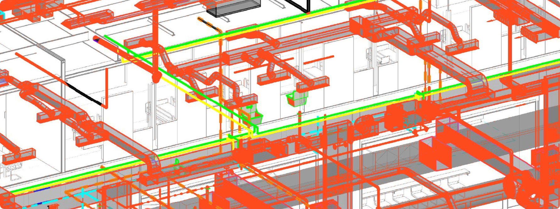
For a BIM design to be successfully implemented, accurate bill of quantities (BOQs) must be generated for the entire building system. Our mechanical BIM engineers will provide highly accurate BOQs to ensure that your BIM design is implemented smoothly.
As part of our mechanical BIM services, we can provide you with the BIM design and mechanical, electrical, and plumbing (MEP) systems in 2D. We are proficient in creating highly compelling and detailed walkthroughs of even the most complex BIM models.
We are a leading provider of mechanical BIM services in India and abroad and can provide highly robust rendered views of the material used in your BIM models and the lighting. In this way, you get a clearer perspective of the property before actual project delivery.
Our expert mechanical BIM engineers understand just how the different aspects of the mechanical BIM models are connected and relate to each other. This ensures that all the components are modeled accurately and that the design is effective and successful.
At Bimplify, we create and deliver sleeve and penetration drawings in a manner that allows for the display and communication of the actual designs when completed. In this way, you get a full picture of the mechanical BIM design.
The safety aspects of a building and its fire prevention and protection systems are the most critical aspects of any mechanical BIM design. Our mechanical BIM engineers are highly proficient in creating designs that minimize the safety and fire risks.
With our mechanical BIM services, you get access to details of the gas piping, drainage pipes, and other piping systems. We ensure that all the systems comply with the shop drawings and that they are clearly annotated and modeled accurately.
In our endeavor to deliver the most effective mechanical BIM services, we also use parametric modeling to present how systems and components will operate and function in real life. We do this by using solid and surface-based design tools.
Our mechanical BIM engineers understand that the piping systems will be running in all directions to source out the gas and water for use in specific locations along the system. Therefore, we provide coordinated 3D piping designs that reflect this reality.